The LSSR slopeable/skewable rafter hanger can be installed after rafters are tacked in place It is field adjustable for skew up to 45° and its innovative hinged swivel seat adjusts up to a 45° slope ML angles provide a 90°connection for medium and heavyduty applications in 2x4 toMay 04, 21 · Splice connections Beam to beam Note To make a clip angle component object that represents a right angle that is made of a standard Lshaped profile and that connects parts type splice connection, it is necessary to create a dummy main part (1) part that exists in a building object and that determines the position number for the assembly or cast unit and the direction ofA splice connection comprising at least two coaxially aligned beam members each having a web, connecting means on adjacent ends of said webs splicing said members in an endtoend relation, said connecting means comprising a tongue extending beyond the end of each of said webs in a plane laterally offset from its respective web and parallel
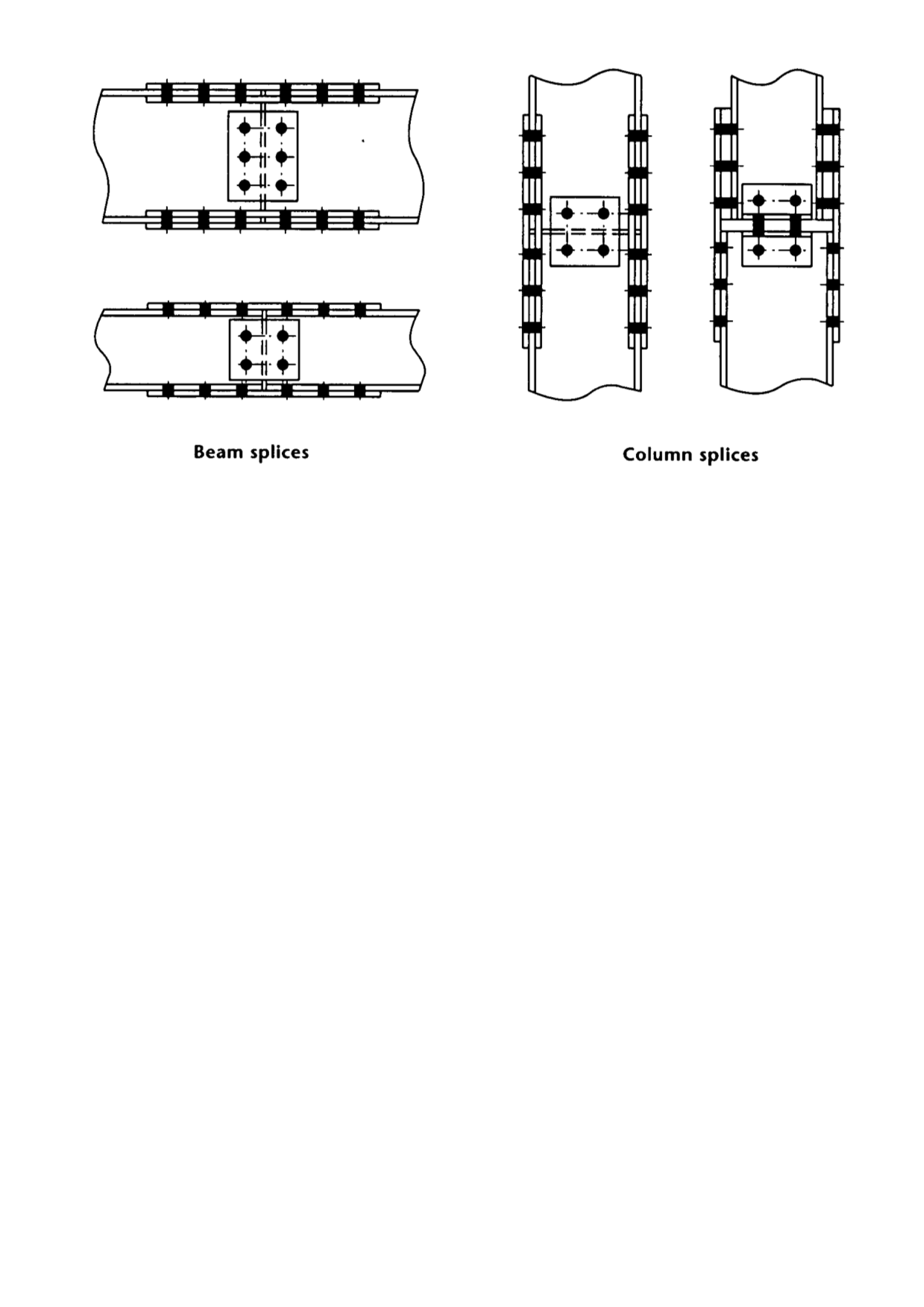
Flange Web Bolted Splice Connection Ram Staad Forum Ram Staad Bentley Communities
I beam splice connection
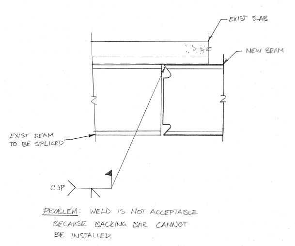
I beam splice connection-That is, the individual flange splices are designed for the smaller design yield resistance of the corresponding flanges on either side of the splice, and the web splice isSep 29, · Connection Details A And Field Splice Of Beam At Shared Scientific Diagram Solved Plete Joint Peration Weld Detailing Autodesk Munity Advance Steel Cjp beam splice in place structural ering general discussion eng section 1 steel framing connections seismic performance of partial joint peration welds in column splices ssef fun is in the


Steel Connections Splice Graitec
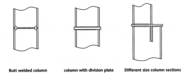
Jul 25, 18 · Splices in beams should be supported by a post or structural column of some sort The post or column should rest on a footing that meets local building code requirements And the beams should be connected to the post with an approved metal connector Beams should be supported by at least 1 in of solid wood over postsContinuous Beam at Column Splice • HSS column is interrupted at continuous beam • For lightly loaded columns, stiffener plates can be used to transfer axial forces • Heavy loads may require a split HSS on either side of the beam web • Beam flange should be wider than HSS Rectangular HSS may be required to fit base plate on beamDetail For a beamtobeam or beamtocolumn connection, as shown on the cover, the use of a concealed kerf plate has proven to be an excellent solution to create this type of detail Either steel pins, as shown, or countersunk bolts can be used for the supported beam connection Summary
Jun 15, 17 · 1 Select node and the two beams connected to them 2 Then click on 'New connection for selected bars' which will create an end plate connection 3 Click in 'Connection type change' where you can select the beam splice typeYou can also use hardware applications like strap ties or nailing plates to further secure the connection Because these connectors are not particularly attractive you will probably want to conceal them behind fascia or on the interior side of the beam In this case we had to splice 2 sections of beam over a center post with a seamFigure 1 Bolted extended endplate moment connection
Bolted splice connections are the quickest and easiest way for steel beams to be joined on site in quality assured manner and avoid the fire risk and quality control difficulties of onsite weldingSteel Beam Splice Connection Design Spreadsheet to BS 5950 Description Essential spreadsheet for designing bolted cover plate splices Allows design of beam spliced connection subject to axial force (tension, compression), shear and moment Includes a very advanced and descriptive diagram showing connection in plan and elevation, it alsoCivilWeb Moment Connection Design Spreadsheet The CivilWeb Moment Connection Design Spreadsheet is an easy to use but powerful suite of spreadsheets for the design of steel moment connections in accordance with BS EN The suite includes separate design sheets for the design of end plate moment connections, beam to beam moment splice
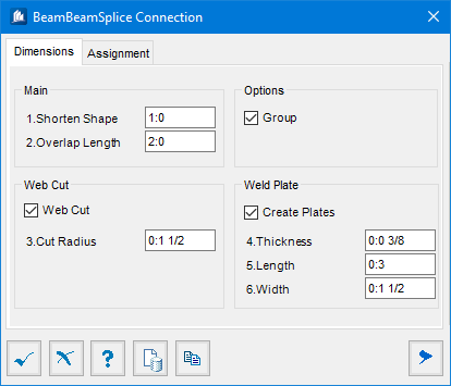


Beam Beam Splice Connection


Steel Beam Reduced Size Welded Splice Connection Detail Steel Beams Beams Weld
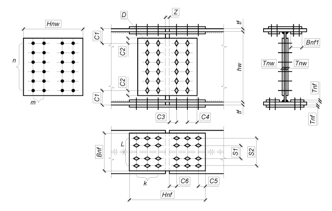
63 Structural Steel Connections, Joints and Details Objective and Scope Met • Modldule 1 Welds – Introduction – Basics of welding – Fillet weld – LRFD of welded connections – Eccentric shear in welds BMA Engineering, Inc – 6000 29 63 Structural Steel ConnectionsBeam Splices The Beam Splices mode enables to design and check the loadbearing capacity of erection joints between I beams with high strength bolts or ordinary bolts using plates or endplates This mode comprises a wide range of designs for erection joints between beams beam splices with plates using ordinary bolted connections with bolts of normal and improved strength and connectionsCommonly, the connection is designed based on the loads at the end of the beam It is required to take strength, type and size of fasteners and strength of base materials into consideration while the connection is designed The minimum length of connection angle should be at least half of the beam clear web depth


Ram Connection 38 Smart Sp Beam Splice Shear Plate Youtube


Aisc Steel Connection Design Software Cisc S16 Steel Connection Design Software
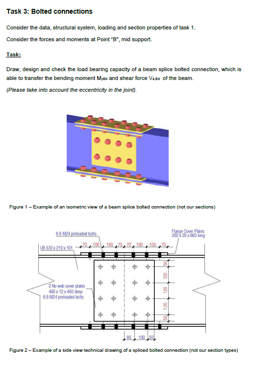
Splice Plate connection (AISC) Tension force kN Plate plate thickness d 1 = 10 mm plate width b P = 240 mm Plate and beam steel A36 length of plate L= 250 mm pl width at base b B = 240 mm f y = 250 MPa 60 1 Angle L100 / 100 / 10 f u = 400 MPa Characteristics/ 1 angle Ag= 1900 mm 2b = 0,9 radii not included x= 28,68 mm b f y = 225 MPaApr 29, 18 · In this post, we are going to look at a design example of beam splice connection (beam to beam connection using steel plates) This joint should be able to transmit bending, shear, and axial forces Let us design a bolted beam splice connection for a UB 533 x 210 x 101 kg/m section, subjected to the following ultimate limit state loads;Design Forces Web Splice Moment in Web Rcffncf Non Controlling Flange R F = Controlling Flange h cf Connection Design Stress in Web (RhFcf Rcffncf)/2 (RhFcfRcffncf)/2 Axial Force Moment Web Connection Design Forces Vuw Huw= (RhFcf Rcffncf)/2x tw D Muw=(RhFcfRcffncf)/2x tw D2/6 Two Rows Minimum e=eccentricity of V uw
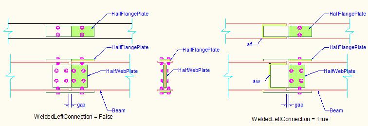


Beamsplices1connection Class
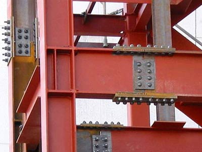


Steel Connections For Beams And Columns Skyciv Cloud Structural Analysis Software
Pinnedfixedfixedpinned or without any release ?Single sided beamtocolumn joint configuration, bolted endplate connection M V 15 3 IPE2 HEB140 1 60 10 30 80 30 240 4 M16 140 p=60 u=10 5 w= To be evaluated Design moment resistance , initial stiffness 0 1 1,0 1,0 M M J J Material S 235A splice welding is a method of joining two members end to end The splice joint is used when the material being joined is not available in the length required It is an alternative to other joints such as the butt joint and the scarf joint


Asi Design Guide 10 Bolted Moment End Plate Beam Splice Connections


Steel Connections Splice Graitec
About Press Copyright Contact us Creators Advertise Developers Terms Privacy Policy & Safety How works Test new features Press Copyright Contact us CreatorsLearn about the predefined types of structural connections There are 130 standard steel connections available in Revit You can load and use these connections in your model Beam end to end Apex haunch* Cranked beam to beam Double apex haunch Front plate splice* Moment column spliceAug , 14 · Dear All, i want to make splice connection on my pinnedpinned connected beam, but which type of release should i define at splice connection point ?


Esdep Lecture Note Wg15b


Adding Hotroll Beam Splice Connections Vertex 19 Documentation
The benefits of standardisation of connections are discussed for beamtobeam and beamtocolumn connections using fin plate and flexible end plate connections Column splices, column bases and bracing connections are also discussed together with a brief mention given to special connectionsDec 01, 13 · It became the most widely used connection in the construction of metal buildings and steel portal frames The primary use of bolted endplate moment connections is to connect a beamtocolumn or to splice two beams together, as shown in Fig 1 Download Download fullsize image;Jun 17, 21 · 56 Haunched connection of a beam to a column achieving goodquality welds on site However, it may be possible to provide bolted splice connections elsewhere in the beam to facilitate transport and lifting, and to fully weld the main connections in the factory (as column 'trees') Stiffened connections
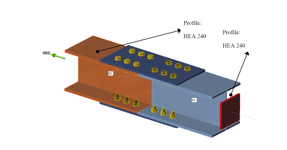


Splice Connections Of I Beam Flanges Idea Statica


Prediction Of The Yielding Moment Of Flush Endplate Splice Connections Using Finite Element Modeling Sciencedirect
Splice connection of continuous equal or different sections with plate and haunches Beam to beam welded simple connection Beam to two beam welded simple connection Contains two options which when activated force the program to always provide stiffeners, one in column to beam connections and the other in ridge connectionsDES 345 –Connection Design Examples NDS CH 11 –MECHANICAL CONNECTIONS Design issues Reference design values Chapter 12 –doweltype connectors (nails, bolts, lag/wood screws) Chapter 13 –split rings and shear plates Chapter 14 –timber rivets Adjustment factors 727 BEAM SPLICE This type of joint is suitable for rectangular columnbeam connection The angle cannot be different from perpendicular The place of connection (on the flange or web of the column) is automatically detected


Welding S Shapes Aws Sec5 Fabrication Beam


Connections Between Isections Steel Construction
A beam splice (or a nonbearing column splice) resists the coexisting design moment, axial force and shear in the beam by a combination of tension and compression forces in the flange cover plates and shear, bending and axial force in the web cover platesBetween the splice plates and beam fl anges 6 When fl ange splice plates are used, single plate shear connections should be used to carry the shear force between the beam and column and to facilitate fi eld erection 7 In direct connections, the beam fl anges and web are welded directly to the HSS wall The limit states in the HSSBeam connections and simple end plate connections 2474 Stiffener Welds Except where the ends of stiffeners are welded to the flange, fillet welds joining transverse stiffeners to girder webs shall start or terminate not less than four times, nor more than six times, the


Ram Connection 22 Smart Fp Beam Splice Welded Flange Plate Youtube


Weldingweb Welding Community For Pros And Enthusiasts
With complete joint penetration (CJP) groove weld splices, AISC relaxes this rule to a height above the beamtocolumn flange connection of at least H (the depth of the HSS column) For field welding, great care must be taken with regard to temporary support and spliceIn the attached verification example, a splice connection of Ibeam flanges is being designed and investigated according to AISC The Ibeams are connected to each other by splices bolted upon beam flanges The beams are loaded by tensile axial force Bolt are loaded mainly inCM 04 Lateral load (D>1/4″) split splice plates fabrication MC inservice MC Table 1033 footnote 2 Beam to Column Connection Serviceability • Beam on Shelf
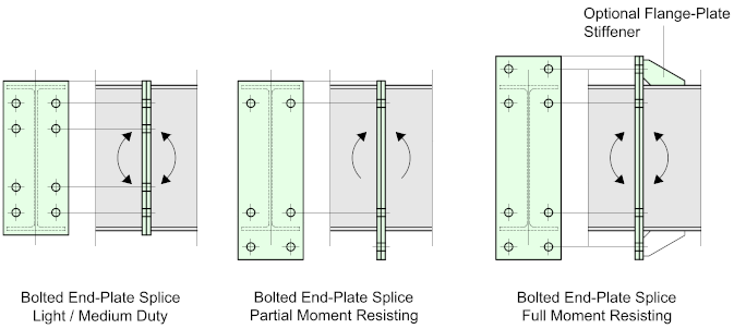


Bolted Beam Splices Structural Detailer


Moment Resisting Timber Connections Ppt Video Online Download
In contrast, in the tie beam splice joint shown in Figure 2, the mortise wall of the tie beam is subjected to doubleshear forces Paralleltograin endload capacity of round mortises in round and rectangular timbers Tendon ducts were spliced, bottom forms placed, and the beam splices and diaphragm splices pouredWeb splice connections for 100 percent of the individual design resistances of the flange and web;The CivilWeb Splice Connection Design Spreadsheet is a powerful and easy to use spreadsheet for the design of steel splice connections in accordance with BS EN The spreadsheet includes a total of 6 different design sheets covering the design of beam to beam splices, column bearing and nonbearing splices and tension splices
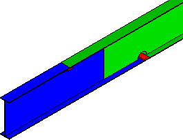


Beam Beam Splice Connection
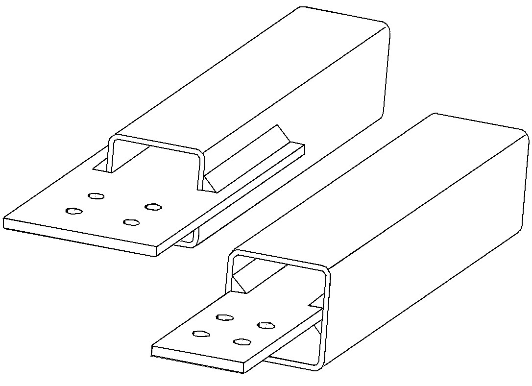


Hidden Bolted Hss Splices Steel Tube Institute
The Bolted WebSplice is the simplest of all the beam splices, it's used basically for joining two beams together and is usually situated immediately above, or close to a point of vertical support Such splices only connect to the beam web and consequently offer virtually no resistance to bending momentsConnections (in beam to column connections in frames) Ideal concentric connections should have only one bolt passing through all the members meeting at a joint Fig 1(a) However, in practice, this is not usually possible and so it is only ensured that the centroidal axes of the members meet at one point See Fig 1(b)Can i define node (splice point) as pinned or fixed ?


1 Beam To Beam Splice Connection Download Scientific Diagram


Beam Splices
May 29, 08 · "If the beam is only 10m long, why is it necessary to add splice connections" It's part of a moment frame, presumably with welded connections to the columns asixth (Structural) 28 May 08 0712 I agree with youngstructural, view your bending moment envelope and provide a splice as close to the inflexion point as possible (for the beam that is)Product Link https//wwwstructuraldetailscivilworxcom/shop/steelframedetails/steelbeamboltedplatespliceconnectiondetaildrawing/Releases pinnedfixedfixed pinned (light


Steel Beam Bolted Plate Splice Connection Detail Drawing Youtube


Connections Between Isections Steel Construction
152x152x37 UC Splice Connection 254x146x37 UB Splice Connection Our Steel Beam Calculator takes the waiting out of calculating It is an instant and easy to use programme which designs in accordance with the most advanced Eurocodes For a minimal investment, the detailed calculations in some instances can reduce steel requirements by over aSplice joint is often used to assure continuity for structural members (beams or columns) along their length The splice plates can be bolted or welded to the main members A welded Splice joint can also be obtained by simply disabling the bolts (the connection between main members and splice plates will be ensured by welds)Sep 22, 18 · Steel Beam Splice Detail Steel beam reduced size welded splice pinned beam splice steel connections aisc steel connection design adding hotroll beam splice connections esdep lecture note wg11 Shear splices civil ering aisc steel connection design cisc s16 steel bridge design hand splice volume 14 full scale tests of welded splices in heavy


Aisc Steel Connection Design Software Cisc S16 Steel Connection Design Software


Hss Splices Steel Tube Institute
Oct , 18 · Beam Splice Connection Calculation October , 18 by Arfan Leave a Comment Z type cantilever beam splices 5 bolted moment end plate beam splice steel connections design according to beam to column connection with end steel connections splice graitec Design Of Bolted Beam Splice Connections According To Ec3 StructvilleConnections (Part11), bracing and truss connections (Part 13), column splices (Part 14), hanger connections, bracket plates, and cranerail connections (Part 15) Our discussion will be limited to the design of fully restrained (FR) moment connections presented in Part 12 and Part 16, Chapter J


Bending Performance Of Splice Connections For Assembly Of Tubular Section Frp Members Experimental And Numerical Study Journal Of Composites For Construction Vol 23 No 5
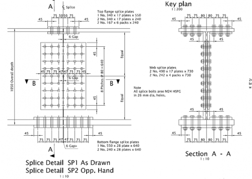


Connections In Bridges Steelconstruction Info


Esdep Lecture Note Wg11


Pin On Structuraldetails Store Catalogue


Welding Splice Design Of Beam Spreadsheet Download Beam Welding Splice Design Spreadsheet
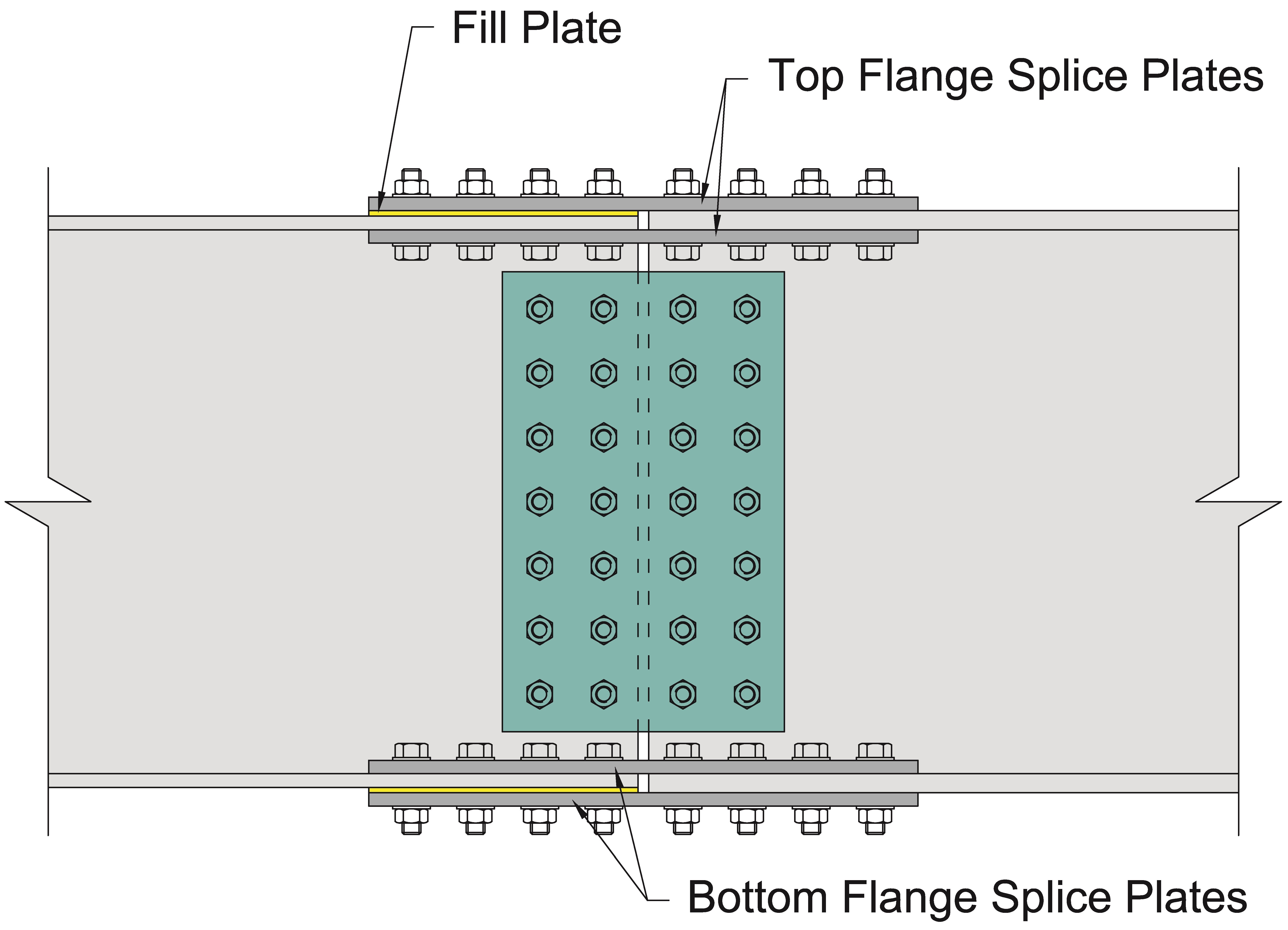


Nsba Splice American Institute Of Steel Construction


4 Splice Connections Etoolkit Beam Structure Screw


Steel Sleeve Timber Beam Splice Connection Youtube


Pin On Career
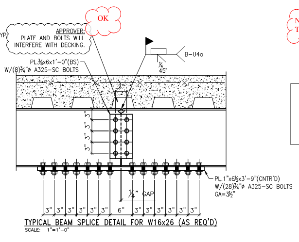


Beam Cover Plate Moment Splice Check Structural Engineering General Discussion Eng Tips
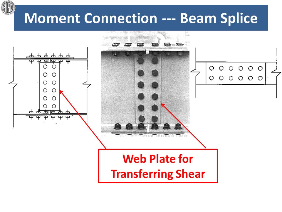


Moment Connection Requires Bolts Outside The Flanges Ppt Video Online Download


Design Of Bolted Beam Splice Connections According To Ec3 Structville


Introduction Beam To Column Connection


Steel Beam Reduced Size Bolted Splice Connection Detail Structuraldetails Store



Steel Connections For Beams And Columns Skyciv Cloud Structural Analysis Software


Esdep Lecture Note Wg11


Flange Web Bolted Splice Connection Ram Staad Forum Ram Staad Bentley Communities


Cjp Beam Splice In Place Structural Engineering General Discussion Eng Tips


Moment Resisting Connections Steelconstruction Info


New Features In Rfem 5 16 01 And Rstab 8 16 01 Dlubal Software


Beam Splices


Task 3 Bolted Connections Consider The Data Stru Chegg Com
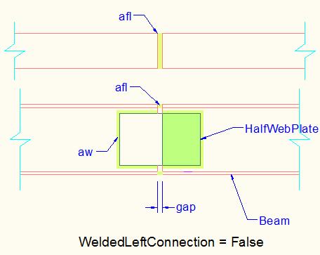


Beamsplices2connection Class
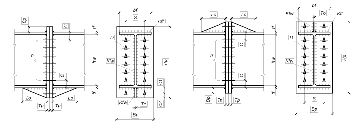


Beam Splices


Adding Hotroll Beam Splice Connections Vertex 16 Documentation
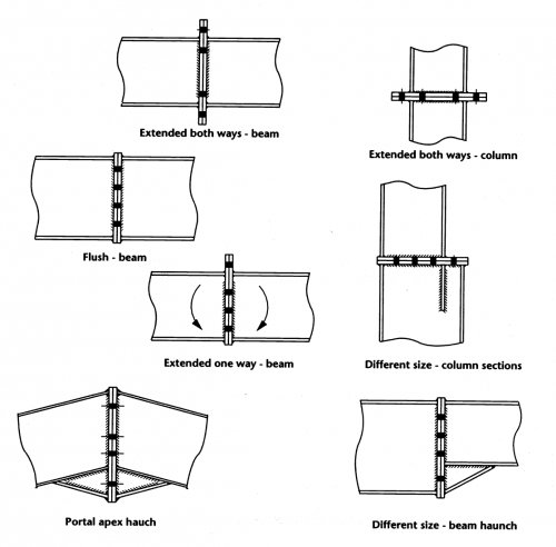


Moment Resisting Connections Steelconstruction Info
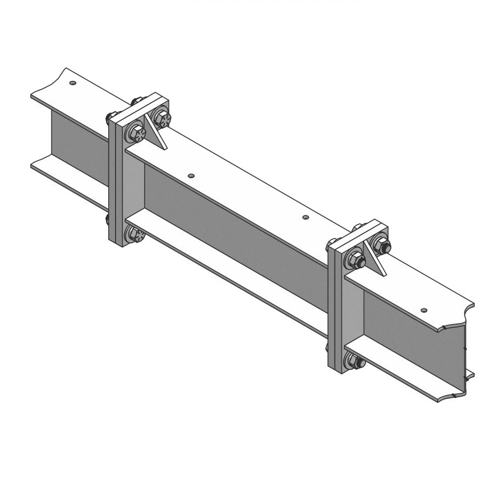


Magnum Mma 818bspg Beam Splice Galvanized Magnum Piering
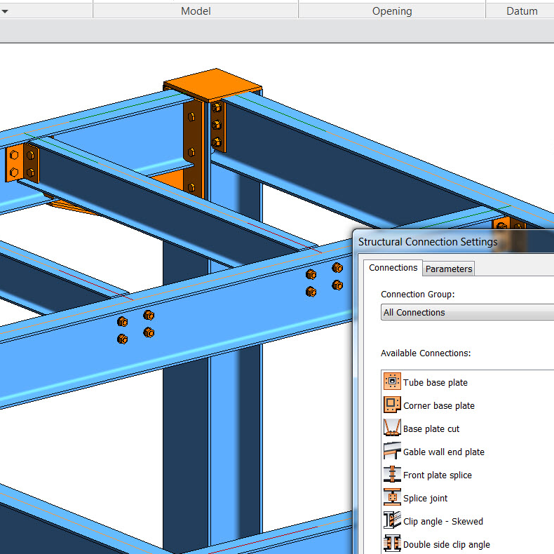


Steel Connections In Revit 17 F Bim And Beam
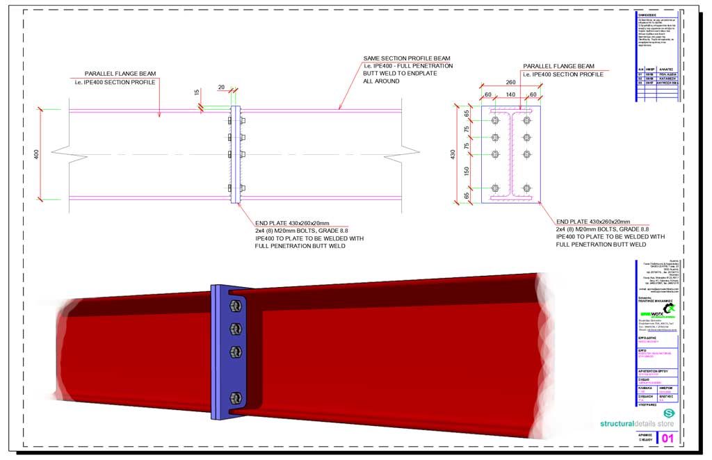


Beam To Beam Endplate Bolted Splice Connection Detail
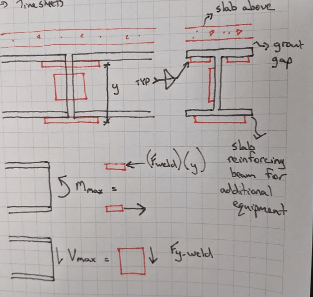


Beam Splice Welded With Limited Access Structural Engineering General Discussion Eng Tips


Steel Sleeve Timber Beam Splice Connection
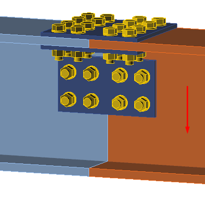


Partial Beam Splice Structural Engineering General Discussion Eng Tips


Connections Between Isections Steel Construction


10 5 Design A Beam Splice Connection For A 533 X 2 Chegg Com


Welded Splice Connection Building Engineering Mechanical Engineering
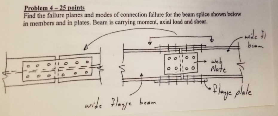


Problem 4 25 Points Find The Failure Planes And Modes Chegg Com
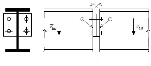


Pinned Beam Splice Steel Connections Fin Ec Online Help


Arcadiabimsystem Euroconnections Beam Splice Cad Software Arcadiasoft


Steel Connections Splice Graitec
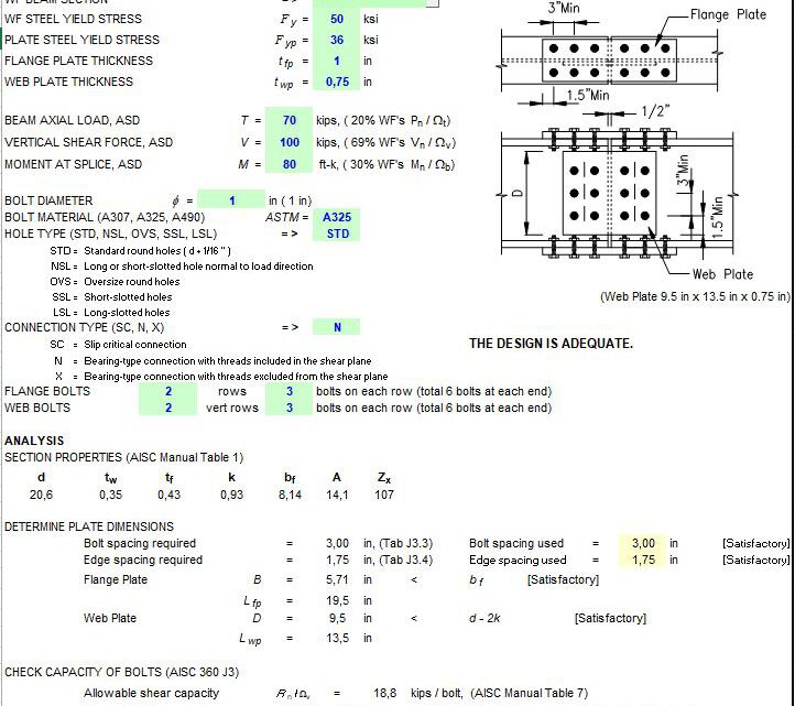


Beam Bolted Splice Design Spreadsheet


Joints Ii Bolted Warehouses With Rolled And Welded Steel I Sections


Code Example Create Beams With Splice Connections Tekla Developer Center


Steel Connections Splice Graitec


How To Understand Staad There Is A Splice Connection With Welded Joint Ram Staad Forum Ram Staad Bentley Communities


Beam Splice Moment Connection


7 Types Of Connections That Can Be Easily Design With Steel Connection Designer Civil Engineering Software Solutions
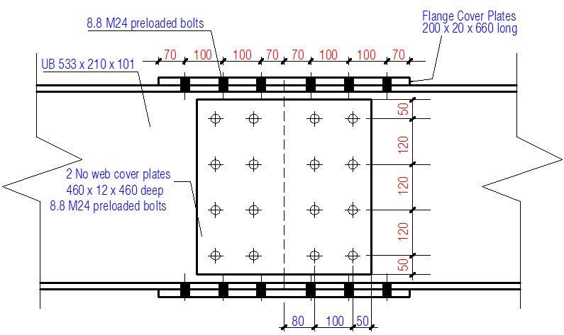


Design Of Bolted Beam Splice Connections According To Ec3 Structville


10 5 Design A Beam Splice Connection For A 533 X 2 Chegg Com


Splice Connection Steel 2 Youtube


Solved Beam Splice Connection 12m Steel Beam Autodesk Community Robot Structural Analysis Products


Beam To Beam Endplate Bolted Splice Connection Detail Beams Steel Beams Structural Engineering


What Is Splicing In Columns Quora
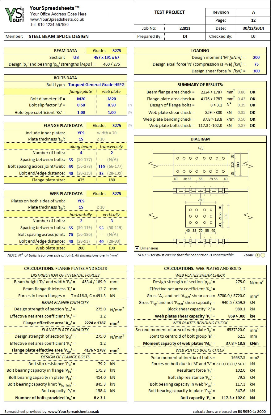


Steel Beam Splice Connection Design Spreadsheet To Bs 5950


Pin On Structuraldetails Store Catalogue


Steel Beam Splice Conundrum
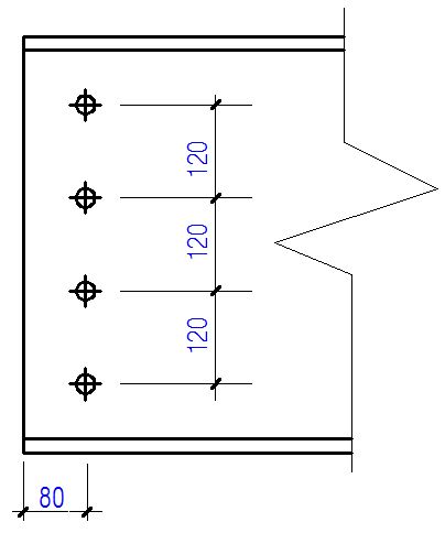


Design Of Bolted Beam Splice Connections According To Ec3 Structville


Beam To Beam Endplate Bolted Splice Connection Detail Roof Eaves Beams Hangar Design


Features


Moment Resisting Connections Steelconstruction Info


Add Hot Roll Beam Splice Connections Vertex Documentation
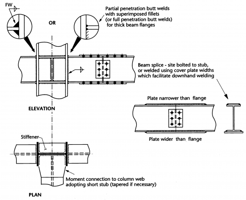


Moment Resisting Connections Steelconstruction Info


Steel Connections Splice Graitec


Connection Details A Connection And Field Splice Of Beam At Shared Download Scientific Diagram
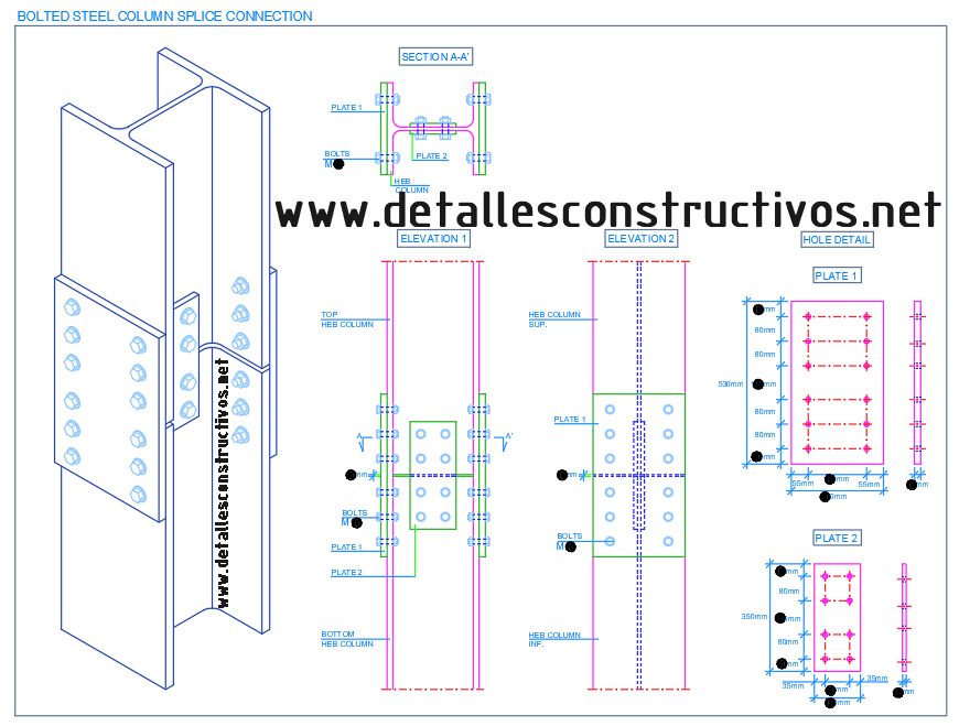


Detallesconstructivos Net Construction Details Cad Blocks
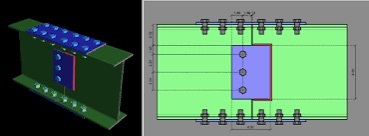


Splicing I Beams Structural Engineering General Discussion Eng Tips
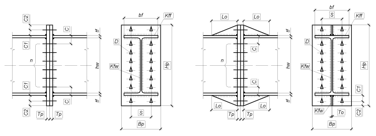


Beam Splices


Seismic Performance Of Z Type Cantilever Beam Splices Of Column Tree Connection Sciencedirect
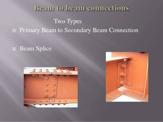


Steel Connections


0 件のコメント:
コメントを投稿